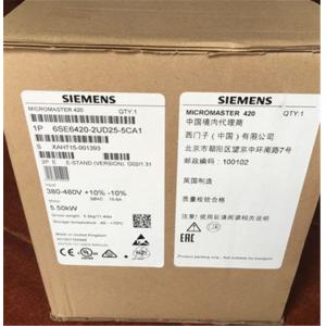
MICROMASTER 420 Types Variable Frequency Drive Inverter Pumps Inverter
Application
The MICROMASTER 420 inverter is suitable for a variety of variable-speed drive applications.
It is especially suitable for applications for pumps, fans and conveyor systems.
It is the ideal cost-optimized frequency inverter solution. The inverter is especially characterized by its customer-oriented performance and ease-of-use. Its large supply-voltage range enables it to be used all over the world.
Design
The MICROMASTER 420 has a modular design. The operator panels and communication modules can be easily exchanged without requiring any tools.
Main characteristics
- Easy, guided start-up
- Modular construction allows maximum configuration flexibility
- Three fully programmable isolated digital inputs
- One scalable analog input (0 V to 10 V) can also be used as a 4th digital input
- One programmable analog output (0 mA to 20 mA)
- One programmable relay output
30 V DC/5 A, resistive load
250 V AC/2 A, inductive load - Low-noise motor operation through high pulse frequency, adjustable (observe derating if necessary)
- Complete inverter and motor protection
Mechanical features
- Modular design
- Operating temperature: -10 °C to +50 °C (+14 °F to +122 °F)
- Compact housing as a result of high power density
- Easy cable connection, mains and motor connections are separated for optimum electromagnetic compatibility
- Detachable operator panels
- Screwless control terminals
Performance features
- Latest IGBT technology
- Digital microprocessor control
- Flux current control (FCC) for improved dynamic response and optimized motor control
- Linear V/f characteristic
- Quadratic V/f characteristic
- Multipoint characteristic (programmable V/f characteristic)
- Flying restart
- Slip compensation
- Automatic restart facility following mains failure or fault
- Internal PI controller for simple process control
- Programmable acceleration/deceleration, 0 s to 650 s
- Ramp smoothing
- Fast current limit (FCL) for trip-free operation
- Fast, repeatable digital input response time
- Fine adjustment using a high resolution 10-bit analog input
- Compound braking for rapid controlled braking
- Four skip frequencies
- Removable "Y" capacitor for use on IT systems (with non-grounded mains supplies, the “Y” capacitor must be removed and an output choke installed)
Technical specifications
| Technical data | MICROMASTER 420 |
| Mains voltage and power ranges | 200 V to 240 V 1 AC ±10 % | 0.12 kW to 3 kW |
| 200 V to 240 V 3 AC ±10 % | 0.12 kW to 5.5 kW |
| 380 V to 480 V 3 AC ±10 % | 0.37 kW to 11 kW |
| Power frequency | 47 Hz to 63 Hz |
| Output frequency | 0 ... 650 Hz, (limitation to 550 Hz in production to comply with legal requirements) 1) |
| Power factor | ≥ 0.95 |
| Inverter efficiency | 96 % to 97 % (Further information is available on the Internet at:
|
| Overload capability | Overload current 1.5 x rated output current (i.e. 150 % overload capability) for 60 s, cycle time 300 s |
| Inrush current | Less than rated input current |
| Control method | Linear V/f characteristic; quadratic V/f characteristic; multipoint characteristic (programmable V/f characteristic); flux current control (FCC) |
| Pulse frequency | 16 kHz (standard with 230 V 1/3 AC)
4 kHz (standard with 400 V 3 AC)
2 kHz to 16 kHz (in 2 kHz steps) |
| Fixed frequencies | 7, programmable |
| Skip frequency ranges | 4, programmable |
| Setpoint resolution | 0.01 Hz digital
0.01 Hz serial
10 bit analog |
| Digital inputs | 3 fully programmable isolated digital inputs; switchable PNP/NPN |
| Analog input | 1, for setpoint or PI controller (0 V to 10 V, scaleable or for use as 4th digital input) |
| Relay outputs | 1, programmable, 30 V DC/5 A (resistive load); 250 V AC/2 A (inductive load) |
| Analog output | 1, programmable (0 mA to 20 mA) |
| Serial interfaces | RS-485, optional RS-232 |
| Motor cable lengths | |
| | max. 50 m (shielded)
max. 100 m (unshielded) |
| | see variant dependent options |
| Electromagnetic compatibility | Inverter available with internal EMC filter Class A; available as options are EMC filters to EN 55 011, Class A or Class B |
| Braking | DC braking, compound braking |
| Degree of protection | IP20 |
| Operating temperature | –10 °C to +50 °C (+14 °F to +122 °F) |
| Storage temperature | –40 °C to +70 °C (–40 °F to +158 °F) |
| Relative humidity | 95 % (non-condensing) |
| Installation altitude | Up to 1000 m above sea level without derating |
Standard SCCR
(Short Circuit Current Rating) 2) | 100 kA |